At a recent game with the ELTC at Northacres park in Seattle, I was inspired by a mod done by one of the players up there (name?). I believe he took some ideas off of my early HUD mod and took them a step further, by mounting the HUD LEDs on the side of the scope with tape, and running the wires through the inside of the tagger body. Though he had the wires protruding from the tagger in places, the idea was there. After seeing and playing with the Tag Master Blaster, I rediscovered how useful those LEDs really are, and sought to find a better way to put them within my field of vision while using a Deluxe. Hacking away at my modded Deluxe again, I came up with this "Scope HUD" mod. This mod, combined with the HUDless HUD Mod, provides for a complete Deluxe tagger experience without the discomfort of the stock HUD unit, or unsightly external HUD mods. Enjoy!
First off, this is a relatively complex mod for me. There's not much electronics work involved, but it's pretty tricky to get the wires all hidden and connected, not to mention getting the tagger back together without pinching wires between the shell halves. Don't do this one as a first mod! If you're really stoked about this one, try some of the other mods first to warm up, or be prepared to buy a new tagger if you screw something up and can't fix it. ;-) Also, this mod requires a "Virtual Scope" accessory, and the end result will be a permanently affixed Scope.
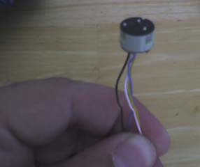
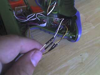
This first thing to do is completely strip down a HUD unit. You can see parts of this process in my original HUD mod. You don't need to do any cutting of plastic this time, because you'll simply be taking the HUD LEDs completely out of the HUD unit. As already mentioned, this goes really well with my HUDless HUD Mod, so if you haven't done that one, you might as well do it as well, since you'll have the parts. You will need to cut some wires in the process of removing the LEDs from the HUD Unit, though. Basically what you want to end up with is the LED unit as pictured here, with as much of the four wires coming off of it as you can get. We'll need this length of wires to channel into and through the tagger. You won't need the connector from the end of the wire, though that will be useful for the HUDless HUD Mod, so leave a couple inches of wire on that for that mod.
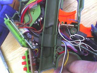
Next up, disassemble your Virtual Scope. On the side that does not have the wall protecting the battery slot, you'll be drilling a hole up through the bottom of the clamp and into the sighting chamber right next to the wall. On that side of the scope, there's a small area that kind of stands away from the "tube" of the sighting chamber. That's where we'll be putting the HUD LED unit. The hole needs to come through about a centimeter from where that little inset area starts, or approximately in the middle of it. In the photo, you'll see that I've drilled through the scope clamp itself. My initial plan was to channel the wires through the scope rail, but that fell through when I tried to get the wires into that part of the tagger. Instead, I drilled another hole at an angle through one of the screw chambers just behind the clamp part of the scope. It's a bit of a challenge to get the wires through these holes, as you don't want the hole to be much bigger than the four wires. In fact, I chose my drill bit based on the one that fit best into the sheathing that I pulled off of the wires after removing the LED unit from the HUD unit.
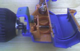
If you haven't already done so, disassemble your Deluxe tagger carefully, and set it aside. In this photo, you can see where the wires have been channeled inside the scope, as well as where they are entering the tagger. The location of the hole on the tagger is based on where the wires are coming out of the scope, as well as the location in the tagger that best allows the wires to be channeled through it with the least amount of interference from other things in the tagger like the LCD panel or screw posts. Be VERY careful when drilling the hole into the tagger so that you don't jam the bit into the back of the LCD panel as soon as the hole punches through. Then, run the wires into the tagger through the hole. As I said, it was a challenge getting all those wires through those many holes. I had to use pliers and mini screwdrivers to guide and pull them a few times.
Once the wires have been channeled through the scope and into the tagger, you can mount the LED unit. In this mod, I place the front face of the LED unit just behind the front edge of that little inset area inside the scope sighting chamber. I superglued the LED icon mask to the LED unit because it comes off easily, and I don't want the LEDs to be too bright inside the scope. Carefully pull the wires through the holes until the LED unit is near enough to its final resting place. Then, very carefully, hold the LED unit in place while applying a few drops of superglue to where it touches the inside of the scope. Hold it in place for at least a minute while the superglue dries. Be careful not to glue yourself to the LED unit or scope shell. It seems silly, but in such tight quarters, it's easy to accidentally do just that. No, I managed to slip past that pitfall this time. ;-) Once the LED unit is secured, you can pull the wires into the tagger and move the (still open) scope up against the tagger half. Reassembling the scope will have to wait until the mod is complete and the tagger is reassembled.
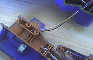
Now we need to channel the wires inside the tagger so we can get them down to the HUD port in the grip of the tagger. I first led the pack of wires behind the cluster going from the dome to the LCD panel, as they needed to be against the shell anyway. Next, remove the wire channel guard from the side of the battery chamber that is protecting the wires going into the grip. This is where we'll be channeling the HUD wires. Lay them in, and carefully replace the wire channel guard, making sure not to pinch any wires in the process. They'll be clamped under the guard fairly tightly, so make sure you have the wires at the length you want into the grip before screwing the wire channel guard completely down. In this photo, you can see the wires already protected by the wire channel guard.
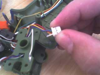
With the wires from the LED unit successfully down in the grip of the tagger, we need somewhere to connect them. The example I'm expanding on had simply taken the HUD connector and brought it up into the grip. Not only am I working with raw wires (no connector on the end any more), but also I want to still be able to use my HUDless HUD mod on this tagger. For me, then, the only choice was to remove the wires from the HUD jack that I needed, leaving the two wires for the headphone. To remove the wires easily, you first need to disassemble the butt plate assembly that has the HUD and Thunder Pack jacks on it. With some play in the wires to work with, you can hold the connector between your fingers, and use a fine screwdriver or other small/sharp object to carefully pry up the little teeth at the base of the connector that are holding the pins in it that the wires are connected to. With a tooth slightly pried away, the pin can be easily pulled out. If the pin won't come out of the connector, then you haven't pried away the tooth enough, or you're prying the wrong thing. ;-) I didn't check the pinouts and schematics, but in my case, all the wire colors matched properly with each other, and removing the white, brown, blue, and yellow wires was the right choice. The red and green wires remained pinned into the connector.
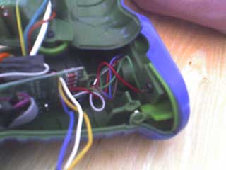
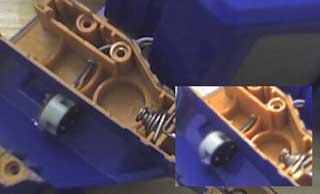
I then reassembled the butt plate assembly. As you can see here, the red and green wires still go to the HUD port, but the other four wires are now completely free from it.
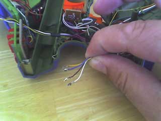
This next highly useful photo shows the four wires from the HUD port with their attached pins. I used the pins themselves to clamp the wires from the LED unit to them. First, I carefully stripped a short bit of each of the wires from the LED unit. Then, passing the tips of the wires quickly through the flame from a lighter, I stripped away the twisted-in insulation fibers. You'll know what I mean as soon as you strip the casing from the ends of the wires. With that stuff gone, the wires are almost ready to connect to the pins from the HUD port connector wires (no longer going to the port :). Before making the connection, I slipped a short length of heat-shrink tubing, the smallest diameter I had, onto the wires from the LED. Then, with my needlenose pliers, I carefully pinched the wires from the LED into the pins from the HUD port leads, matching them color for color, banking on the fact that they properly matched in function as well.
After the wires were successfully crimped together, I did a quick test to make sure the LEDs functioned properly. Good thing the battery tray can be placed in the chamber for a full connection even when the tagger is taken apart. :) With a successful test out of the way, I slipped the heat shrink tubing over the pins now serving as wire connectors, and shrunk them down with a hairdryer. The next step is to put everything back together again. With so much more wiring in the grip of the tagger, it's even more important to pay close attention to where all the wires are running while putting the two halves of the tagger back together. It's easy for them to be pinched under a screw post, between the shell halves, or something else in there, so watch closely, and go slowly. If the parts don't meet and snap together completely without force, then it's likely there's a wire being pinched somewhere. With everything safe and out of the way, screw the tagger back together. NOW you can reassemble the scope itself. Watch out for the little square nut that often falls out and make sure it's in place properly. Getting the scope back together will be tricky, since you have to put the clamp piece on the scope rail of the tagger, and then assemble the scope halves around the clamp piece, all while taking care that no wires are being crimped and that the scope pieces are all in place. Assuming you took care and all is well, you should be able to fire up your tagger and take a look down your new Scope HUD!
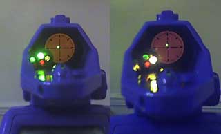
Here we have a couple crappy photos of the Scope HUD in action. The lights all do what they should, with the lock-on flashing while locked, the red tagged flashing when tagged, and the yellow icon flashing when getting a hit confirmation. It's REALLY nice to be able to see this information right in the line of sight while lining up targets. This mod is so cool, IMHO, that I'm wishing the Drone had a HUD port for me to put this mod into that tagger with. It also makes me want to play with this tagger again, except that it also has the Auto-Fire On Lock mod that's much too tempting to use. Anyway, if you're in the area and want to see this tagger with all it's mods, just come to an ALTC game!
I hope you enjoyed this mod. Thanks again to (name) who took my HUD Mod to the next level, and to Shoot the Moon and Hasbro for designing the LEDs in the Tag Master Blaster such that this mod idea popped into my head. This mod is the next level again for the HUD mod, with the TMB as final inspiration.