Recently I added two LTTO TMBs to my existing collection of 4 Deluxe and 4 Drone Taggers. As soon as we played using the TMBs I realised that the dome hit flash made quite a difference to the experience. It acted as a constant reminder that you were aiming for the Tagger, not the person, and was very satisfying when you made a hit. I aimed and scored as one of the opposing team ran down a slope between trees, and the hit flash told me instantly that I'd made a great shot. So I wanted to upgrade my Deluxe and Drones to match, and naturally hit the internet.
The resulting modification was inspired by and largely follows the work of others, with this in mind I'll start with a few URLs to important source material you would be well advised to have a look at before going any further.
The first site to visit is the original modification design which includes the circuit and fairly detailed instructions for making the modification to the LTTO Drone Tagger http://www.tagparty.net/blog/?p=16. I wanted to improve on this modification if possible by avoiding the need to drill holes in the side of the Tagger, which obviously meant mounting the LEDs inside the red dome. An internet search revealed that others had already done this to, http://tagmasterz.imect.com/text.php?id=11.
I should point out that this is going to be an 'idiots' guide, I figure those who know this stuff will just work from the original design whilst those who don't have much experienced (like me) would rather know too much than too little.
|
|
So now I had a basic circuit design (reproduced above), component details and a pretty good idea I could make it all work. The next step was to choose the major components; referring to the circuit design you need the following:
So you have now decided on types and quantity of components, ordered them and they have arrived. You are ready to go, only other things you need are screw drivers, wire cutters, something to strip the insulation from the wire, a soldering iron and solder. Now I'll take you through the work step by step with pictures to try and make it as easy as possible.
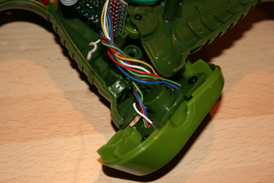
First step is obviously to open the Tagger, to do this remove the 9 screws from the Tagger body, the two screws in the reload handle and the 2 screws in the handle base plate where the Rumble and Hub connectors are. Gently ease the two halves of the body apart. If the trigger and shield buttons fall out don't worry just put them to one side. You will find that both sides of the body have wires attached and they are therefore a little bit cumbersome. Picture below is looking into the handle and shows the main half on the desk with the other half propped up on top. The green printed circuit board (PCB) in the foreground is your first concern.
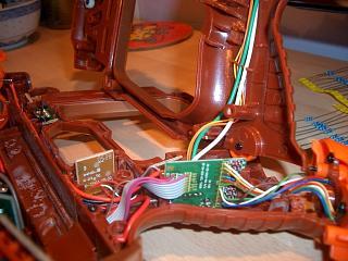
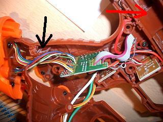
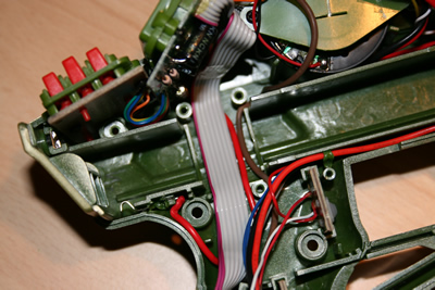
To make access easier the green PCB can be eased out from its retaining slots, to do this more easily you have to remove the wire guide cover that allows the wires to pass through the battery holder compartment. You can see the cover clearly in the picture above on the right (red arrow). Remove the three screws and remove the cover.
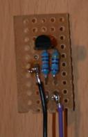
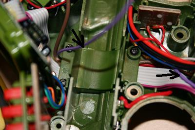
At this point you can make up your own little circuit board for mounting inside the Tagger. I cut the matrix board to be 15mm tall by 25mm long, this is a nice size to mount into the handle, roughly where the arrow indicates (black arrow). I glued my board to the little plastic 'pillar' there, though be careful not to block the nut that the handle base plate screws into.
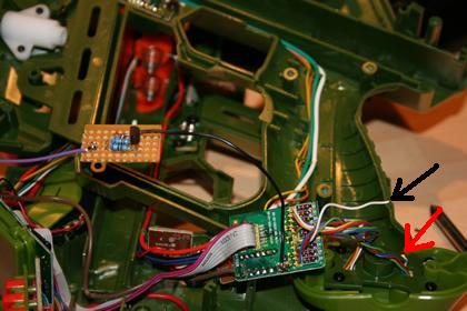
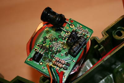
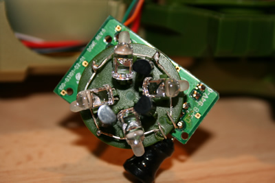
You can make up the circuit in any physical layout you like, my layout can be fairly clearly seen in the photo below (taken during another modification, hence the change from orange to green Tagger). Lots to see in this picture, note:

You can find the wring for the Rumble port on the Deluxe at http://home.comcast.net/~ferret1963/DeluxeConnectors.HTML.
Once the three wires are connected you can tuck the new circuit board away, run the LED cable through the battery compartment covering it nicely by putting back the plate you removed when you were freeing up the green PCB. The LED wire needs to be run up to the dome which can be gently removed from the Tagger body.
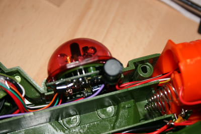
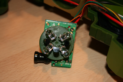
The red dome cover can be removed from the PCB it is attached to (in three places) either via a little gentle pressure, or if it has been stuck into position, but heating the plastic legs carefully from the underside of the PCB. A little force is required but not a lot, you can see the three mounting holes clearly in the picture below.
At this point you can choose to test your switching circuit before wiring up the dome. I ordered a few extra LEDs and soldered the required number, 4 in my case, in series. I then carefully loaded the batteries, after checking that the Tagger was cleanly laid out and nothing where it shouldn't be. Hit the reset button, do this every time you put the batteries in, and then started the Tagger in quick game mode (hit trigger switch twice) before I got a helper to power up another Tagger. I then carefully connected the LED lead from the switch circuit (my mauve wire) to the correct end of my LED series and the other end of the series I carefully pressed against the battery pack positive spring (the one the red wire goes to - see pictures). [Warning - be careful not to touch both the battery springs simultaneously otherwise you will short the battery pack which would not be good]. Now when the Tagger under modification takes a tag the LEDs should flash. If it does flash then you are on the home straight, if it does not then remove the battery (this keeps you and the Tagger circuits safe) and then check everything carefully. If the LED flash is very weak, as mine was on the first Tagger I modified, check the circuits as you may have a a bad solder joint or a wiring problem - turned out I had the ground and LED wire backwards!
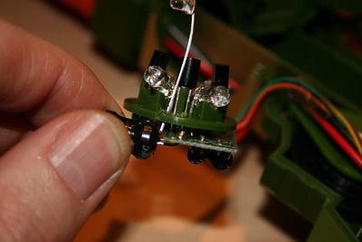
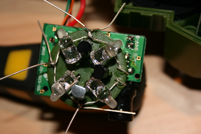
You now have a working circuit and all the most difficult wiring completed. You just have to finish the dome modification which is actually quite straightforward. The dome mod is hard to explain in words so look at the pictures below whilst reading the text, it should help it all make sense. Basically you need to start by creating two holes in the plastic component-plate. You can either do this by heating a resistor wire and pushing it carefully through and working it a bit to increase the hole size, or by carefully drilling a 1mm hole using a suitable hobby tool. I used the melting technique but another person who made this modification used the drill approach (your choice). Try and angle the hole outwards, this makes it easier to bend round the LED cable once you insert them through the holes. Now basically you fit the first LED, bending its wire back around the plastic component-plate, this gives a solid start. Then tying the remaining LEDs together one at a time and soldering them together as you go. [Warning - make sure you get the LEDs in the right orientation, i.e. positive to negative to positive to negative etc., otherwise they will never flash, and rewiring would be messy and annoying.] You can control the LED positions and tightness of the LED loop around the plastic component-plate fairly easily. As I had 3mm LEDs I mounted them directly under the IR LEDs which were already there. Once all of them are fitted thread the last LED lead through the second hole and carefully tighten. Cut off any stray LED leads, you are now ready to attach the last two cables. Attach the cable from the switch circuit (mauve wire in pictures) to the LED negative [shorter wire], I found it easiest to thread this wire between the legs of the large capacitor. Then attach a new wire (red in my pictures)to the positive LED lead, this needs to be long enough to also reach the battery pack springs.
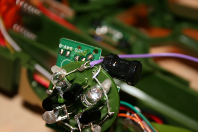
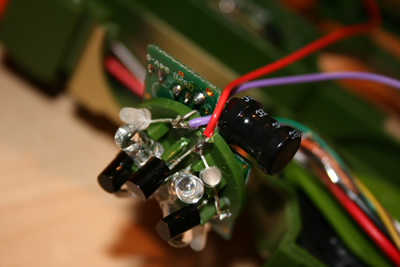
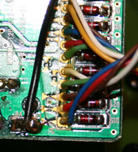
You have two routes to take the final wire (my red wire) to the battery, I went through the battery compartment via the orange 'firing' laser barrel, I could do this easily as I'd used single strand wire that stayed in the shape I'd bent it. Alternatively you can go back through the wire guide you used to thread the LED cable from your switch circuit. Your choice, I was a bit lazy as really the cable guide is the neatest route. You just need to solder this last wire to the positive battery terminal, do this by soldering to the large red cable (red for power) that is already solder to a small orange component which is in turn connected to the spring. Don't solder directly to the spring.

That is more or less it. Before rebuilding you can re-fit the battery pack, hit reset, and then run a similar test to the one you may have done earlier when you were checking out your switch circuit. You should now be able to rebuild everything, including pushing the dome cover back on top. There is no need to glue the dome cover back onto the PCB, the Tagger body will hold it well enough.
You have completed your first modification, now all that remains is to test it thoroughly before modifying any more. Testing is up to you, I did the following:
After all that I was pretty confident I'd done everything successfully and I did the others I had waiting. Though I'll be honest I didn't test the others quite as carefully, once you get the hang of it the rest are much easier.
OK, that is it, all finished. I hope this helps everyone who wanted to have a go at this modification but is a little nervous. Most of the credit goes to the original designers who specified the switching circuit, proved the modification in the Drone and showed you could mount hit LEDs comfortable in the dome. Plus the Tagger designers who provided such a versatile toy. I just added a few more pictures to their work.
If you still have questions there are lots of good people on the message board at http://members5.boardhost.com/lazertag/index.html?1188237456 who will gladly help.
Good luck and happy Tagging.